Making water-cooled magnetic field coils
For trapping atoms in a magneto-optical trap (MOT) one usually requires magnetic field gradients on the order of tens of G/cm. To produce such gradients water-cooling the magnetic field coils is typically not required. In our configuration we operated the coils at 20A current, which led to gradient of roughly 17G/cm and increased the coil body temperature to approximately 70°C.
When we recently started imaging and counting single atoms in a dual-species MOT
(Citation: Bhatt
& al.,
2021)
Bhatt, R.,
Kilinc, J.,
Höcker, L. & Jendrzejewski, F.
(2021).
Stochastic dynamics of a few sodium atoms in a cold potassium cloud.
, it became quite clear that higher field gradients would be very much beneficiary. Especially for potassium, the atomic cloud was very dilute, which means that the signal spreads over a big region on the camera sensor. A high field gradient (on the order of 200G/cm) compresses the atomic cloud and concentrates the fluorescence on a smaller area, which reduces the influence of stray light.
Furthermore, higher magnetic field gradients would enable us to implement a quadrupole magnetic trap stage between the MOT and the dipole trap stage on the road to condensation
(Citation: Lin
& al.,
2009)
Lin, Y.,
Perry, A.,
Compton, R.,
Spielman, I. & Porto, J.
(2009).
Rapid production of $^87\textR\textb$ Bose-Einstein condensates in a combined magnetic and optical potential.
Phys. Rev. A, 79(6). 063631.
https://doi.org/10.1103/PhysRevA.79.063631
. The atoms would be captured from the MOT in the magnetic trap, after which an rf-evaporation scheme would follow. After transferring the cold atoms into a mode-matched dipole trap, the atoms would be evaporatively cooled by lowering the trap depth until condensation is reached. As we had some troubles transferring the pre-cooled atoms from the MOT (after a molasses stage) directly into the dipole trap, this technique should lead to a more efficient transfer.
Basically there are four different approaches to coil systems:
- Non-cooled coils. Wind enamelled copper wire around frame of desired shape and pass current through the wire. This approach is typically used in simple systems. There are no problems with possible leaks, but the coils will heat up.
- Hollow-core coils. A hollow copper tube is used and water flows through the internal water-channel. This is the standard approach, which is used in most experiments in Heidelberg. However, it has numerous drawbacks: High water pressure, inefficient cooling, expansive, hard to recreate the same coils.
- Bitter electromagnet. Circular metal plates are stacked on top of each other with current flowing in a helical path through the electromagnet. Holes in the copper plates allow for efficient cooling. These coils solve most of the problems of the hollow-core coils, but have other problems like complex assembly and possible leaks.
- Bulk-machined electromagnet. Similar to the bitter coils, these coils are produced from a bulk copper piece. Here, a spiral is cut into the copper and filled with epoxy. The water is in direct contact with the top layer of the copper (Citation: Roux & al., 2019) Roux, K., Cilenti, B., Helson, V., Konishi, H. & Brantut, J. (2019). Compact bulk-machined electromagnets for quantum gas experiments. SciPost Physics, 6(4). 048. https://doi.org/10.21468/SciPostPhys.6.4.048 .
After fruitful discussions with the Brantut group, we decided to follow their approach with the bulk-machined electromagnet. The main idea for these coils is that you take a piece of copper and carve out a spiral without opening the coil to the outside. Then you fill the gaps between the thin copper layers with epoxy and, once the epoxy has hardened, machine the copper piece to your desired shape. A PEEK cap with the same dimensions as the copper coil is screwed onto the coil. This cap is U-shaped, such that the cooling water can flow in a channel between the PEEK part and the top copper surface.
Design considerations
When designing the coils, there were a few constraints to keep in mind:
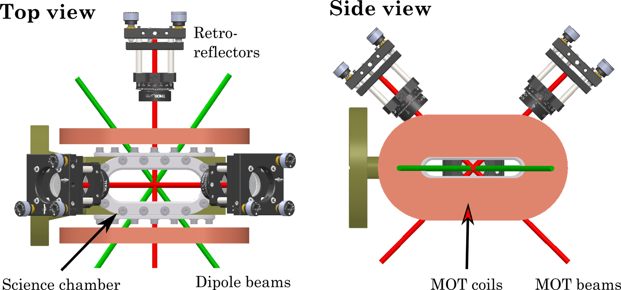
- The elongated viewports of the science chamber enable very good optical access, which should not be blocked by the coils. Therefore, we decided to match the shape of the viewports and go for race-track shaped magnetic field coils. The width of the inner hole should be large enough to let the dipole beams pass through (see figure below).
- The coils are operated in anti-Helmholtz configuration, which gives a homogeneous field gradient at a distance $d = \sqrt{3}R$, with R: effective radius of coil. The distance between the coils is set by the width of the science chamber (roughly 75mm), which is why the effective coil radius has to be matched.
- The number of windings is one of the parameters, which determines the magnetic field gradient. Similar to our previous set of coils we decided to go for 40 windings, which meant a gradient of 1G/cm/A. To still keep the coil rather compact we chose a pitch of 1mm/winding. Thus, between each 0.7mm thin copper winding there would be a 0.3mm layer of epoxy.
![]()
Sketch of our science chamber with magnetic field coils, laser beams and optics.
Manufacturing the coils
When manufacturing the coils we mainly followed the detailed description given in
(Citation: Roux
& al.,
2019)
Roux, K.,
Cilenti, B.,
Helson, V.,
Konishi, H. & Brantut, J.
(2019).
Compact bulk-machined electromagnets for quantum gas experiments.
SciPost Physics, 6(4). 048.
https://doi.org/10.21468/SciPostPhys.6.4.048
.
The spiral was created using a wire erosion machine (wire diameter 0.25mm). As we started carving out from the middle towards the outside, the weight of the middle copper piece was dragged down like a spring, which hindered the operation of the machine. To circumvent this issue, a plate had to be placed below the coil as a support. The coil would rest on this plate and it featured a hole, where the erosion wire passes through.
After carving out the spiral, the distance between the copper layers was not at all uniform, which is why fiber-glass spacers were inserted into the ridges. This stabilizes the spiral and also acts as an insulation between the layers.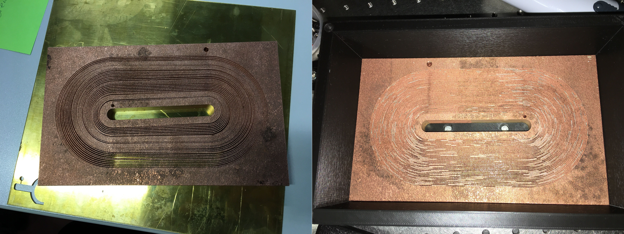
In the next step, epoxy was filled into the gaps. This was the most challenging part for us, as we did not have any experience with epoxy at all. First, we made a mould for the coil, put the coil inside, filled it with epoxy and put it under vacuum using an old pre-pump. This was supposed to remove any air bubbles from the epoxy, which could cause problems in terms of leak tightness. However, this plan did not really work out for us, as the epoxy was sticking too much to the mould (even though we had used wax to stop that from happening) and the epoxy was not going into all gaps evenly. Moreover, there were still some air bubbles remaining.
For the second try we, therefore, decided to fill the coil with epoxy using a syringe. In the end we had to fill some cavities with extra epoxy, but then (finally) had a leak-tight copper coil.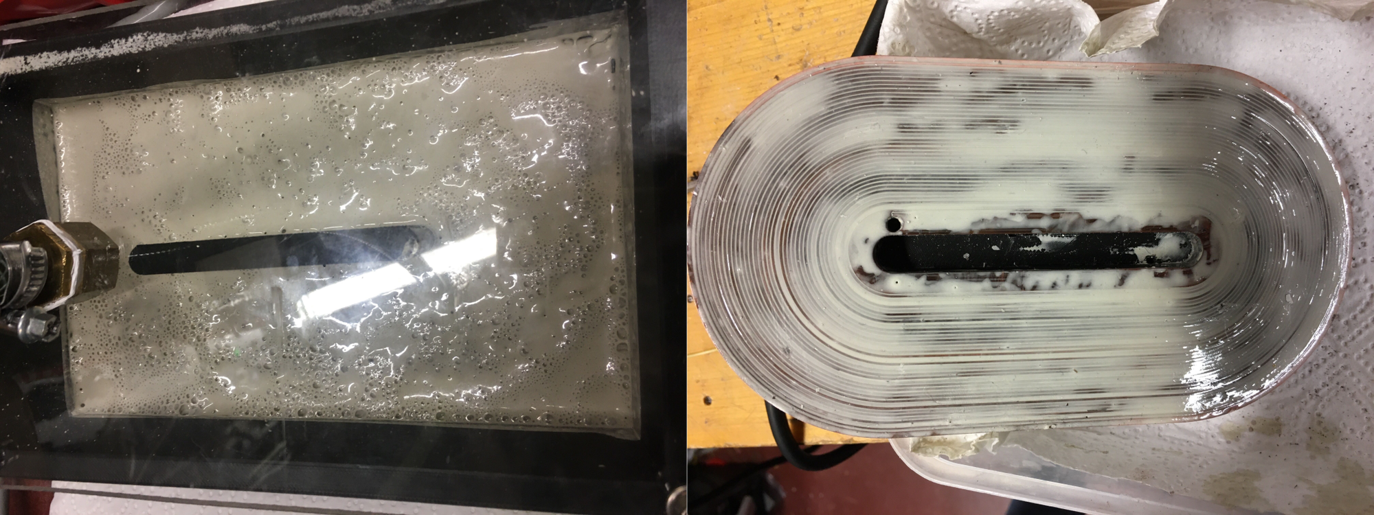
Water cooling
The cooling water flows in a water-channel between the coil body and a Peek part. The PEEK part is screwed to the copper piece with eight titanium screws. For that we made threads into the copper and used PEEK inlets for electrical insulation (figure left). To make the connection between the two parts leak-tight, we used O-rings on the inner and outer side of the PEEK part. Even though these parts are (like the copper coil) shaped like a race track, standard EPDM O-rings can be used (we used this website to find the correct dimensions with respect to cross section and inner diameter).
In the beginning, we had some issues with water leaking out of the titanium screw holes on the PEEK part, but were able to get rid of these leaks by using Teflon tape and tightening the screws some more.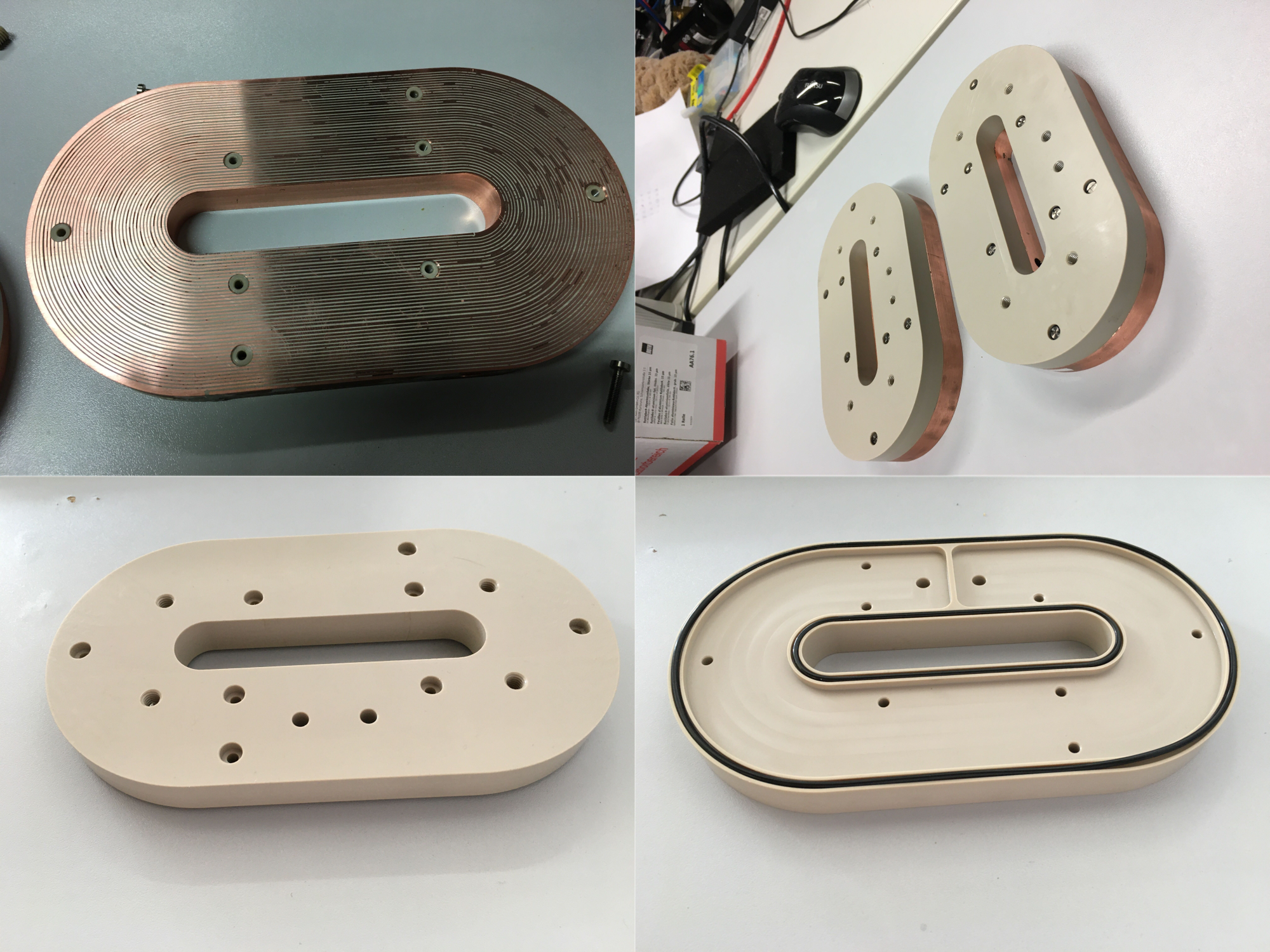
Chiller. We went for the Riedel SC21 chiller, which is very compact, simple and inexpensive. As it is on the lower side with respect to the cooling power it can provide, an upgrade might be required to operate the coil at 300A with negligible heating.
Installing the Coils
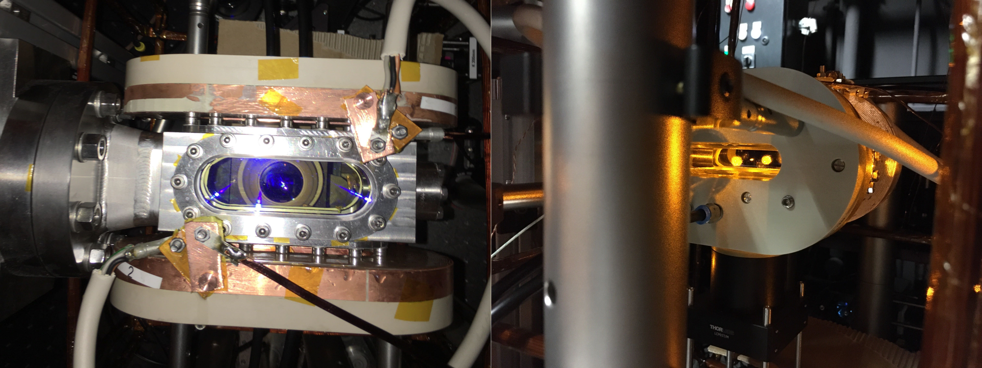
Electrical connections. To operate the coils in proper anti-Helmholtz configuration, we have to pass the current through the coils in opposite directions. At high currents, required for the magnetic trap, thick copper cables or copper bars are needed to pass the current from power supply to the coils, as thin ones would heat up dramatically. For initial testing we used thin copper wires and were able to recover the MOT (shown in image below).
The fast control of the current in the coils, during an experimental sequence, is implemented through a simple IGBT switching circuit.
Furthermore, an interlock interrupts the electrical connection in case the coils get too hot. The hottest points on the coil are the outermost and innermost windings, as these are not in direct contact with the cooling water. Therefore, we placed K-type thermocouples at these points. An Arduino Uno reads the temperatures and shuts down the power supply in case the temperature goes above 50°C.